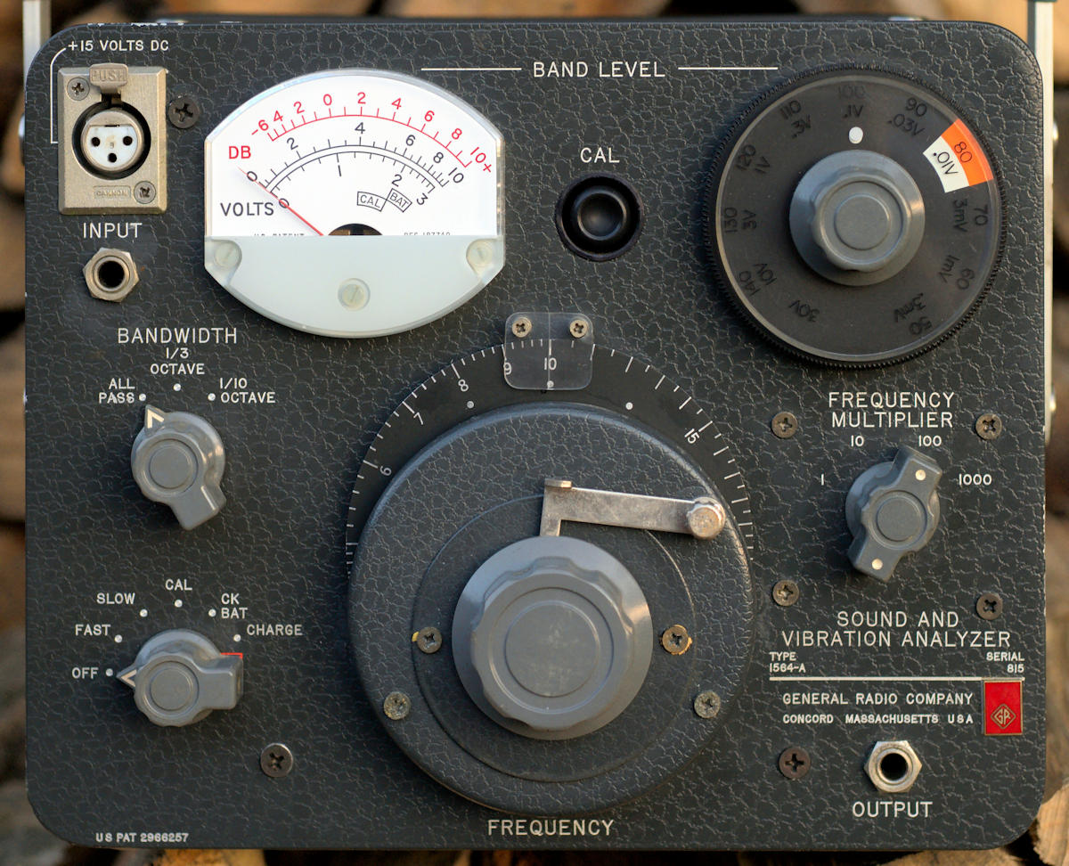

The GR 1564-A, and the non-A version, are calibrated tuned amplifiers suitable for use with microphones or accelerometers. The 1564-A covers the audio region in four ranges, from 2.5 to 25,000 Hz. There are three bandwidth settings, ALL PASS, 1/3 OCTAVE and 1/10 OCTAVE. The unit covers 50 dB to 140 dB fs in 10 dB increments and can also be used as a calibrated AC voltmeter from 0.3 mV fs to 30 V fs. 15 VDC is provided at the input connector to power the GR 1560-P40 preamp for an additional 20 dB of gain, bringing the measurement range down to about 25 dB. Fast and slow response can be set but the unit has no provision for weighting like A-weighting or C-weighting. The GR finger-pinching flip top case is standard. They were produced in large numbers, from 1963 to at least 1978, a run of at least 15 years, though as of 2019 they seem to be getting scarcer on the big auction site.
Operation is straightforward and is well covered in the manual. One should also read the General Radio Corp. Handbook of Noise Measurement for a good overview of the topic. I should note that the instrument has some long internal time constants, so a certain amount of meter movement is normal when powering up or changing ranges. The less PC might also refer to it as "banging from stop to stop." It can take quite a few seconds to settle down after adjustments. If you use the 1560-P40, it too takes quite a while to stabilize.
I've found the 1564 very reliable and most can be returned to factory spec with only minor service. The odd capacitor or germanium transistor can require replacement, but even capacitor failure is rare, considering that most are about 50 years old. One thing that does fail, as expected, is the internal NiCd battery pack. This is a 16 cell affair (19.2 VDC) in one of several styles and serves not only as a low noise power supply for fully isolated operation, but as additional filtering and voltage regulation during AC operation. The unit will not operate correctly unless a functional battery pack is present, or unless a suitable "cheat" is employed as described below. Note that an old NiCd battery pack can create noise, probably due to internal leakage paths going short or open. Shorted cells can sometimes be temporarily refurbished using a short high current pulse, but don't do it with the battery installed.
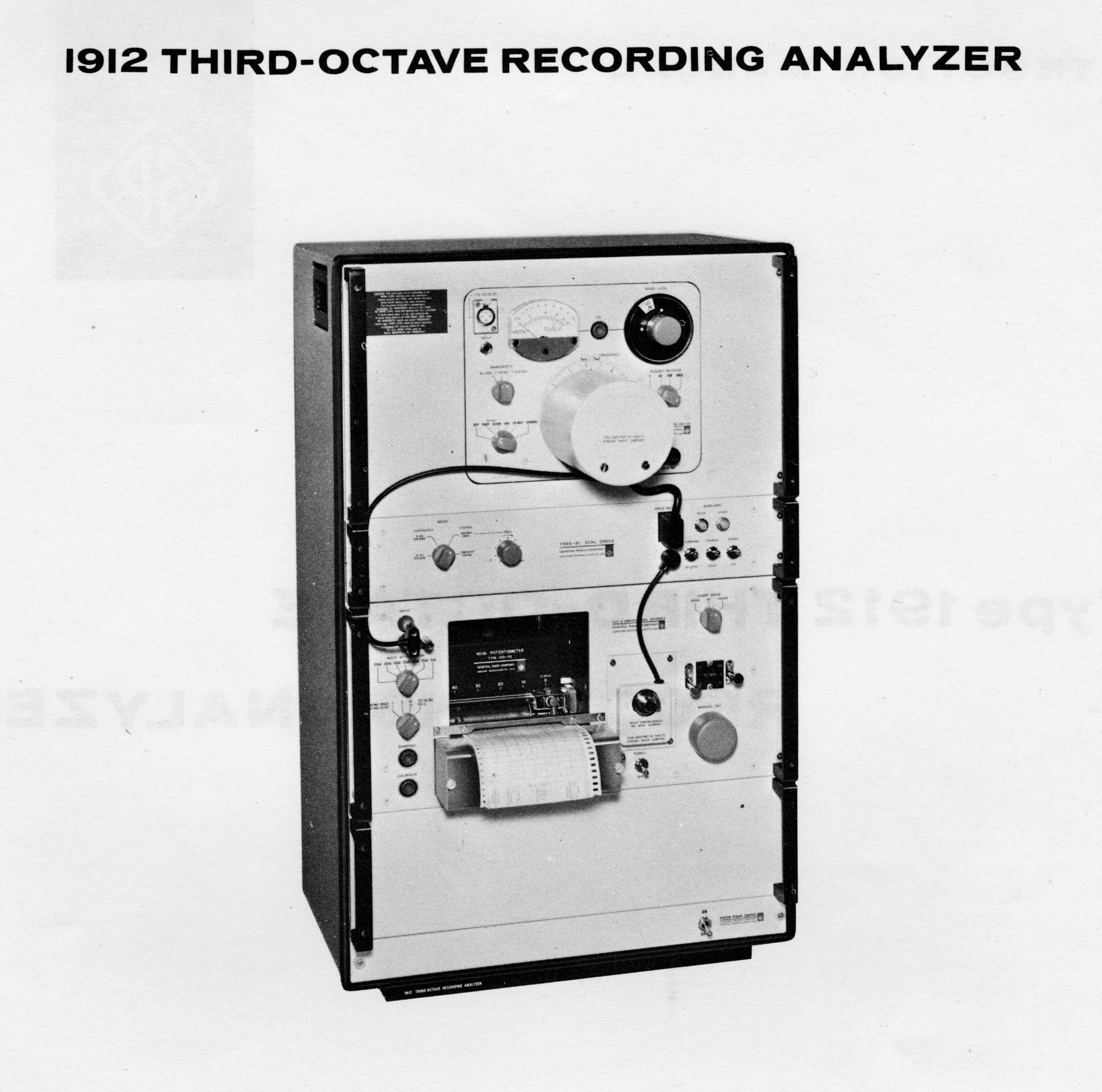
The 1564-A can be coupled to the GR 1521 Graphic Level Recorder for automatic frequency response and other measurements. The original arrangement used a chain to drive the filter dial from the chart recorder, but an electronic stepper motor drive was offered around 1968. The system could be assembled by the user, or purchased as a turn-key system- the Type 1912 Third-Octave Recording Analyzer. It included the 1564-A, 1564-P1 Dial Drive, 1521-B Graphic Level Recorder and ten rolls of chart paper. With its rack cabinet, the assembly weighed in at a whopping 95 lbs.
The first order of business is to set the selector switch to CHARGE for a few minutes and see if the battery will come up to an acceptable level on the front panel meter. If not, it needs replacement. I've made up battery packs from 16 generic AA NiCds, but you'll need a way to weld the terminals. A reasonably serviceable cheat can be made if you consider how a battery pack operates. It will charge to a given voltage, then simply hold at the level, burning off excess current as heat. If the charging level is low, this works fine. Note that NiMH cells shouldn't be trickle charged for a long period, so they don't make a good NiCd substitute. If you don't want to build a battery pack, you can simply use a large electrolytic capacitor that's been shunted with a 19 volt zener or series combination of zeners. Use 2 watt or larger. This won't run the instrument on its own, but will regulate the voltage and provide some filtering for AC operation. A capacitor of 10,000 µF should work, but the higher the value the better, if it will fit. Use 25 VDC or more.
The manual contains some basic functionality checks and you should do those to evaluate the instrument. If you get into troubleshooting, remember that the transistors are germanium, which have low turn-on voltages. In-circuit measurements may thus be shunted by leakage or turn-on. I sometimes carefully remove transistors, but always install high quality TO-5 sockets before reinstalling them.
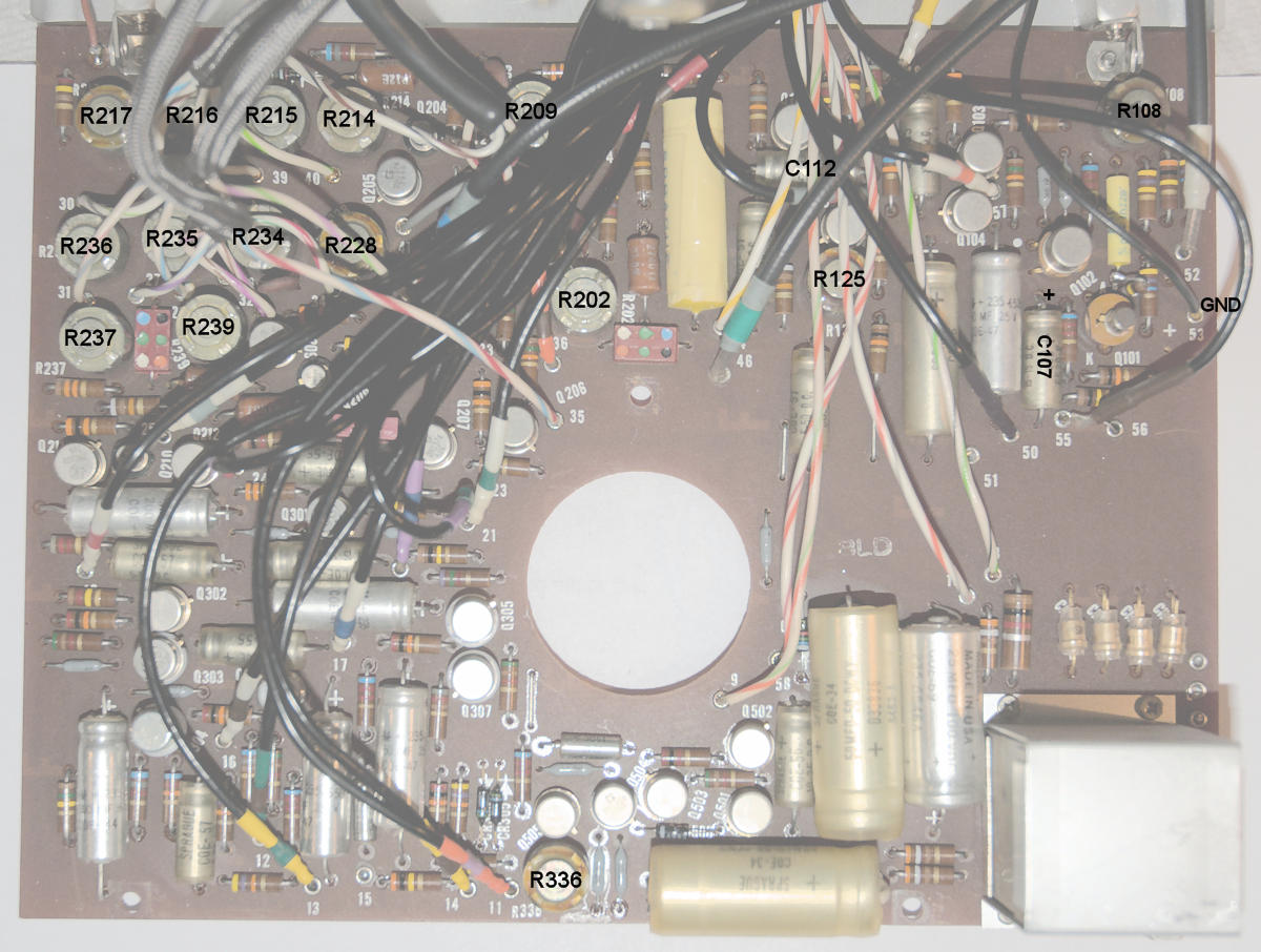
The manual covers filter alignment well, but omits the bias adjustment for the first stage along with the calibration of the calibration circuit. Biasing the first stage appears easy enough, though I don't know if there are any finer points to observe. The bias pot is R108, in the corner of the board, away from all the other adjustments. Measure from the positive lead of C107 to ground and set R108 for a reading of 8.6 VDC, the center of the range shown on the schematic. The pots are mostly clearly marked but here's a helper photo you can print out for reference.
To fold out the pcb, remove the screws at the lower edge and in the center. I find that it's better not to remove the screw near the transformer, but to remove the associated screw that's just around the edge on the metal panel. The board will then have more clearance to fold out without scraping anything.
The calibration circuit gives the amplifier circuit positive feedback, causing it to oscillate. It uses a diode limiter to stabilize the amplitude. The gain of the amplifier is adjusted to put the oscillation amplitude in the CAL region of the front panel meter. Because feedback oscillation is so sensitive to gain, this gives an accurate gain setting for different microphones, or direct readout, through the use of the internal sensitivity control.
The most important thing to understand about the calibration circuit is that it has no effect on the normal operation of the amplifier. The only thing that changes the gain of the amplifier is the setting of the front panel CAL control, the one with the flush rubber thumb knob.
Internal adjustments of the calibration circuit, including the internal sensitivity dial, only control the amount of positive feedback. This causes you to change the front panel CAL control, changing the gain of the amplifier for subsequent measurements. It's extremely important to understand that point, as we're going to work backwards to calibrate the calibration circuit.
The procedure is pretty simple. First, set the range switches for the 3 volt range in all-pass mode. Using the phone jack input (unless you have a handy XLR connector), drive the unit with 3 volts RMS at 1 kHz, measured with a known good DVM. Adjust the front panel CAL thumb knob for a reading of exactly 3 volts. The amplifier is now calibrated for 3 volts and hopefully all the other ranges as well. Now we calibrate the calibration circuit.
Open the unit and locate the internal sensitivity control. There's a line (not the reference line) that should line up with the pointer when the dial is turned fully clockwise. If this isn't the case, loosen the dial and make it so. Try to keep tension on the spring washer under the dial when tightening the screws.
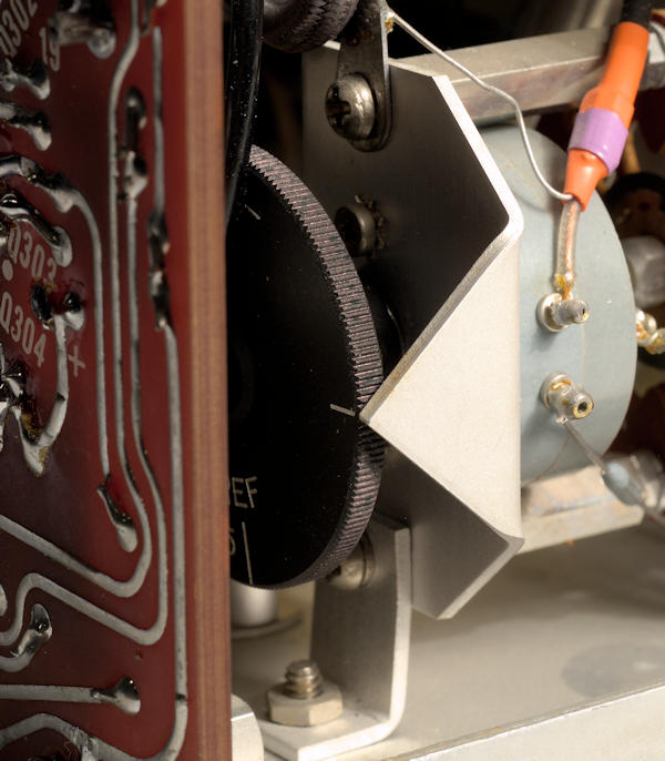
Set the internal sensitivity dial to the reference mark. The reference mark is for when the instrument is used for direct voltage measurements. Watch out for line voltage on the rear circuit board around the transformer! Set the range switches so the white dots are at top dead center. Put the unit in CAL mode and adjust R336 (bottom center of the circuit board) so the meter reads in the center of the CAL area. This is also +4 dB on the red dB scale. The calibration circuit is now calibrated.
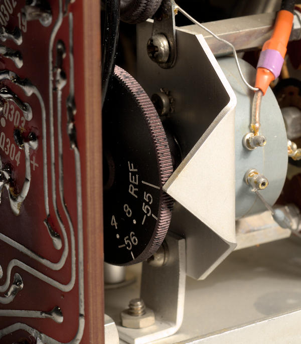
The typical GR ceramic microphone has a sensitivity of about 61 dB below 1 volt/µbar (-61 dB). For mic use, set the sensitivity dial to match the microphone in use. See the manual for settings based on accelerometer capacitance.
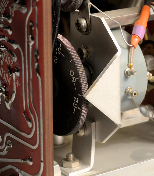
Hopefully it was that easy, but I'll mention a few pitfalls. Out of the case, the unit is very sensitive to 60 Hz pickup. That's the reason for calibrating at 3 volts. Ten would be even better if your generator can do it. One could make up a shielded box from some metal window screen or aluminum flashing, to work at lower levels, but I've never tried it. The meter may read slightly differently in different positions. They shouldn't, but balance is never perfect and age probably takes its toll. Thus, check your work with the unit in the chassis and in the position you intend to use it the most. Some DVMs roll off before 1 kHz. If yours does, calibrating at 60 Hz will probably work just fine too. Note that the signal output has a small amount of hum. It's just the positive tip or half of a sine wave, which suggests they got some of the cap charging loop of the power supply in common with some signal ground. If I find it, I'll add a fix for it. It's probably of no real consequence unless you run the output into a spectrum analyzer.
When you use a microphone, the internal sensitivity dial should be set to the sensitivity of the microphone, not the reference line. If, however, you have an SPL calibrator like the 1562, 1567 or similar, I'd always set the amplifier gain with that, and not use the internal calibrator at all. If you do that it doesn't matter where the internal sensitivity control is set. It has no effect on normal operation. It's common for calibrators to output 114 dB, so set the range switches for that, apply the calibrator to the mic and adjust the gain (CAL knob) for a reading of exactly 114 dB. Remember that the calibrator must fit the microphone, either directly, or with a suitable adapter to keep the cavity volume correct.
I also have the 1559 mic calibrator as found on my GR pages. If I calibrate mic sensitivity using that, and then calibrate my 1567 114 dB source based on the mic voltage, the 1564 agrees perfectly if the internal dial is set to the mic sensitivity determined by the 1559, and the usual cal process is followed. That suggests the voltage calibration using the reference mark as given above, is very accurate.
It's hard to keep links current so I won't add them here, but the following are interesting documents you should search for:
C. Hoffman
last major edit September 6, 2019