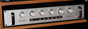

The ARC SP-4 preamp was ARCs first solid state preamp. It was controversial at the time and some say it almost destroyed the company. Opinions about the sound quality are all over the map but based on dealer comments and my listening, it wasn't exactly world class. Age has also taken its toll by now and I found my unit nearly unlistenable with LPs after a brief evaluation. Conventional steady state measurements showed nothing seriously wrong with it, but the music had no life.
The unit was 37 years old, the capacitors were getting tired and it seemed a tune-up might reveal something that could be done to improve it. I'm not a fan of arbitrarily replacing electrolytic capacitors unless they measure poorly or show physical signs of age but the caps in the SP-4 were on the verge of trouble. The dissipation factors were a bit high, the positive leads showed some corrosion and a few values were starting to rise; they sometimes do that near the end of their lives. Later tests also showed high DC leakage on a couple parts, so this unit was more than ready for a full re-cap. (I later refurbished another SP-4A and every original aluminum electrolytic in it was bad. Many caps were a small fraction of their original value and the troubles included both a short circuited and a completely open cap.)
The SP-4 uses ARCs potted analog modules. That greatly limits what one can do in terms of modifications because the circuitry is unknown and inaccessible. All one can do is take a guess and work with the external circuitry.
One thing that stood out was the use of many tantalum capacitors. On the plus side, tantalum caps are very stable and don't age or wear out. On the minus side they have a reputation for poor sound quality. Tests I've made show that they can have unusual non-linearity. Since we don't know where the tantalums are connected in the modules, it's hard to estimate any effect them might have on sonics, but replacing them seems like a safe bet.
Thus, the plan was to replace all the aluminum electrolytics with new parts, and as many tantalums as possible with aluminum electrolytics. Modern caps are often smaller than they were 37 years ago, plus the SP-4 has plenty of space to work with, so this turned out to be an easy job, with the exception of the RIAA section. Many of the small tubular caps were replaced with radial styles that fit just as well.
Please read through everything before starting. You may decide to leave the RIAA section alone, depending on your skill level and ability to measure the parts.
This wasn't a difficult re-cap job, but there is always some risk of damaging the unit or damaging yourself if you apply power with the covers off. If you can't take full responsibility for modifying your equipment, and have sufficient electronic knowledge to do so safely, please use your "back" button now. This page is not for you!
The preamp was built on a single sided PCB with no mask or legend. The traces are reflowed tinned copper with no plated through holes. Without plated through holes to provide some strength, it's very easy to lift pads and traces if you use too much heat, or even if you don't. Tread gently. Many of the parts are simply floating in space above the board, relying on the stiffness of their leads and the strength (I use that term loosly) of the traces for stability. In spite of the solid chassis and the very high quality parts used, the internal construction is somewhat fragile. In a high vibration environment it would quickly shake itself to pieces. No matter- in a home installation it will hold up fine. If you ship one, be sure it's double boxed and packed with great care. I stuck with the original construction and also mounted the new parts somewhat off the board. This made it very easy to adapt the radial parts to the axial connection points.
My SP-4A had the optional moving coil cartridge head amp. It was the head amp that got me started on this because one of the caps was showing the first signs physical leakage- a brown discoloration of the rubber overcoated end seal. High grade caps are often sealed with epoxy, but the ARC caps use what looks like blue silicone rubber. Or maybe it turned blue over the years. I'm not sure if the material was applied by the capacitor manufacturer or by ARC, but I've never seen silicone used in this application before.
Removing the head amp is a bit of a pain. You have to remove the side of the preamp, unsolder the power, input and output wires and carefully angle the housing out. I replaced the axial electrolytics with radial caps and extended one lead. A strip of weatherstripping was applied in the housing to stabilize the new caps. The head amp also uses some 1000 uF 6 volt tantalums. I didn't like leaving these but didn't have anything that would fit in the same space. The head amp is the only part of the unit where space is at a premium. Though it isn't clear how these caps affect the modules, I believe the sound quality might be improved if a suitable aluminum electrolytic could be found to replace them.
While you have the head amp out, try to find some #10 hex nuts with attached lockwashers (KEPS nuts). These are much easier to deal with in the cramped space near the front panel. Be sure to retrieve any dropped hardware that might lodge in the circuitry!
The SP-4 used many 6 volt rated aluminum electrolytics. Low voltage aluminum electrolytics have poor dissipation factor and poor reliability compared to those rated at 16 volts and above. I believe they can also have linearity issues. There is no good reason to use 6 volt caps other than size and size isn't much of an issue here. I used 25 volt caps in almost all locations and believe there is a sonic benefit to doing so.
Low voltage tantalum caps have two issues. They don't sound good and they fail shorted. They have moderately low dissipation factor and are probably fine when used for energy limited power supply filtering and decoupling, but they have no business in any location even remotely related to the signal path. Some would say that includes the power supply as well, but I don't have any evidence that they cause a problem there, other than the risk of a short circuit if they fail. In a modern design it would be unusual to see tantalum caps used at all because they have no real advantage over today's aluminum electrolytics. Note that they do have low DC leakage, so when in doubt replace them with low leakage aluminum electrolytics.
If this writeup has a "theme" it's the use of high quality commercial grade capacitors in 16 volt or higher versions. Feel free to use whatever you're most comfortable with, but my advice is to avoid the lowest voltage caps and lean towards the low dissipation 25 volt and higher parts. The regulated supply voltages in the SP-4A are ±20 VDC so any rating above that is acceptable. The main power supply caps should be rated at 40 volts or higher.
If you play LPs the RIAA amplifier section is the heart and soul of a preamp. The rest is just switching and buffering, important of course, but if the RIAA section isn't first rate nothing else matters.
We need to address the RIAA section first because you are going to replace various capacitors that are mounted on top of other parts that will also need to be changed. Depending on the parts you use, the top or bottom of the board may prove to be the better choice. I put the input cap on the bottom of the board, the padding caps on the bottom and the electrolytics on the bottom. Do whatever gives you the cleanest installation for the parts you use. I repeat the caution that the traces here are small and fragile, so use extreme care while removing and replacing parts.
The RIAA equalization is set by two 750 kΩ resistors that provide feedback around the modules, plus two RC pairs consisting of 48.7 kΩ in series with 0.0068 μF and 1.00 kΩ in series with 0.0022 μF. In a normal opamp circuit it's not difficult to calculate the correct values for these parts, but the ARC modules have less gain than a normal opamp. Thus, the values giving the most accurate RIAA curve have to be fine tuned by trial and error. ARC probably got the curve they desired but in my opinion they didn't hit the target as well as they could have. It's close but you can do better. They also fudged the input impedance a bit. It's 50 kΩ but should really be 47 kΩ.
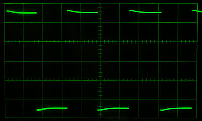
I spent quite a while simulating the circuit, making guesses as to the contribution of the modules and fine tuning them based on actual measurements. The thing that bothered me was what amounted to an overshoot on transients. It's really just an RIAA error but that's how it affects the signals. My goal was to smooth this out without replacing every part in the unit, and I think I've accomplished that. The original curve has a slight rise of about 0.5 dB at the low end, and I've left that alone. The response from 100 Hz to over 20 kHz is now flat within a couple tenths of a dB. The square wave response is nearly perfect. For more info on square wave testing of RIAA preamps you might want to locate the paper New Factors in Phonograph Preamplifier Design by Tomlinson Holman.
ARC either bought very close tolerance capacitors, or they selected them. My original 0.0022 and 0.0068 caps were dead on value, better than 0.1%. Unfortunately those caps are Mylar. Back when it was built Mylar was probably considered a good choice. Today it's generally accepted that polystyrene and polypropylene are sonically superior. I'm not sure I can hear the difference and if you want to leave the original caps alone that's OK. If you can measure caps accurately you may want to change them to polystyrene or polypropylene.
Getting the RIAA curve right requires specific value caps. The target values are 0.006875 μF and .002240 μF and you'd like to be within about 20 pF of those value. If you left the original caps, assume they are exact and pad them to the new values with small 5% or better silver-mica or C0G/NP0 caps. Don't use any ceramics other than C0G/NP0. 75 and 43 pF would be good values.
If you're installing new caps, measure and pad as needed. Note that I purchased 5% caps and was able to get just two caps with a good match out of the ten I bought. If I were doing it again, I'd buy 20 or more just to be sure of a good assortment. They were inexpensive polypropylene block caps from Digikey, so we're not talking a big investment here.
Next, change the 48.7 kΩ resistor in series with the 0.0068 μF cap to 46.4 kΩ. Change the 270 Ω input resistor to a metal film. I don't know if it truly makes a difference but a high gain input doesn't seem like the best place for carbon composition. Change the four 100 kΩ input resistors (in the "funlets") to 88.7 kΩ. These are in parallel with 100 kΩ on the other side of the input cap and the new combination will give you the standard 47 kΩ input impedance.
I have no idea why they chose such a large input coupling cap of 150 μF, much less a tantalum. Replace that cap with a 2.2 μF or larger polypropylene or polystyrene cap. You can also use a good electrolytic, but it should be low leakage and match the original polarity. The value could be anything between 2.2 and 150 μF. Anything over 2.2 μF will make no difference within the audio band. There is some voltage on the input of the modules and they set the output offset with very high value resistors on the inputs. Capacitor leakage would upset the balance.
You need exact values for the RIAA curve to come out right. Close isn't good enough, so if you don't have the parts specified, leave it alone. You can't improve anything with other than exact values. Here's the top of the board showing component locations. The flux and contact cleaner haven't been cleaned off yet!
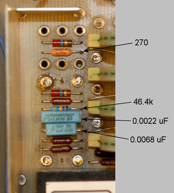
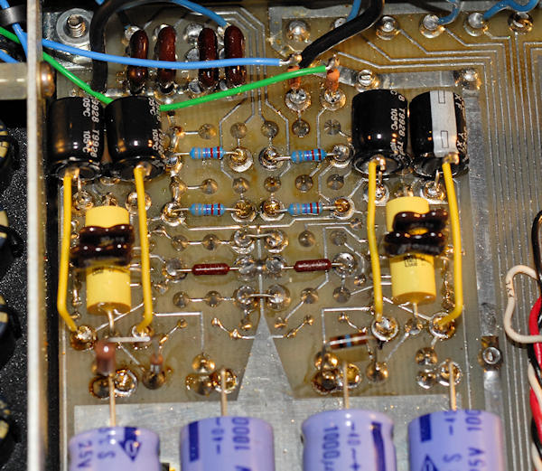
Here's the bottom of the board showing the new loading resistors, input caps, padding caps and new electrolytics.
If you elect to test the RIAA curve, this design was done using the inverse network published on hagtech.com and optimized for square wave response. There are various inverse networks published with slightly different response curves. You have to choose something and I believe the hagtech is one of the better ones. The most useful square wave frequency is about 300 Hz. The usual frequency response curve was also measured; be sure your equipment is also flat over the measurement range. This is the somewhat non-flat response that the value changes fix. After the changes you get a normal looking square wave that I didn't photograph because it was, well, just square.
In all honesty I'm not sure I can really hear a difference after these RIAA changes. I'm too close to the measurements so my biases are hard to suppress. I think the sound is less fatiguing and a bit smoother, but it's debatable that I could identify the changes in a blind test. I no longer have golden ears, if I ever did. Because the traces are so fragile and the work is fussy, and because the preamp can be made reasonably good, but not world class, I question the wisdom of the less experienced trying to make these changes.
Now I'll show some photos and describe each one underneath. Note that these photos were taken prior to my RIAA changes so that section will not be up to date. You'll still need to change the electrolytics there, but go by the instructions above, not what you see below.
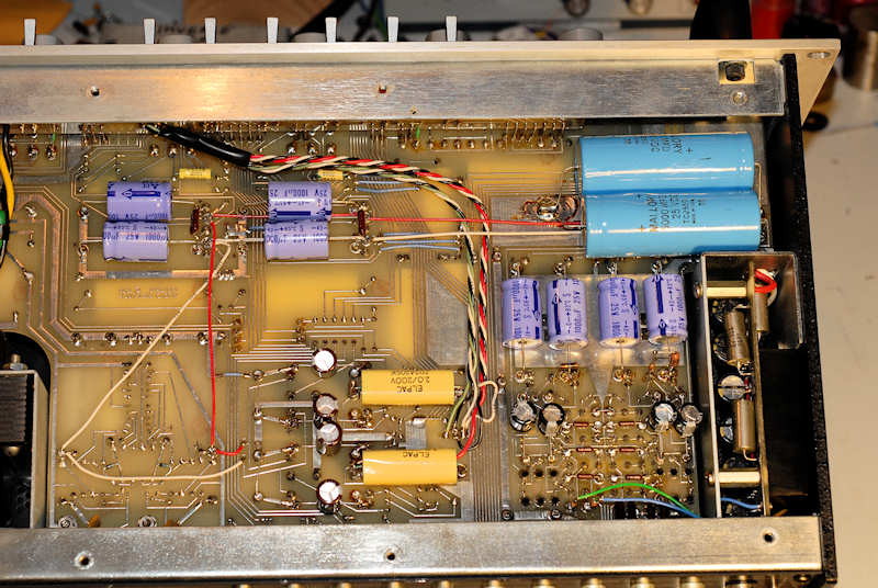
Replace the 8 1000 μF 25 volt electrolytics. It should be possible to find near exact 1000/25 axial caps. All these caps mount in eyelets. They float above the board slightly so use a thin piece of cardboard or file folder to space them above connections that could pierce the plastic jackets. It's little realized but capacitor manufacturers will tell you the plastic jackets are for marking and appearance only; they are not designed to provide electrical insulation. Observe polarity!
Replace the 4 330 μF tantalums (lower mid-left) with radial aluminum electrolytics. Again, use 25 or 35 volt caps for their improved dissipation factor and improved linearity.
Replace the 4 150 μF tantalums associated with the RIAA section with radial aluminum electrolytics. I used 220/25 here. More on the polarity with the next photo.
You can see the optional head amp to the right. The ends of the new 3300/16 FC caps are visible as are the silver tantalum caps that I didn't replace. The blue and green wires are the outputs of the head amp (I replaced the original wires so the colors are non-factory) and they each solder to a 270 Ω resistor that then goes to the appropriate eyelet. My unit was odd in that it originally had the wires going directly to the eyelets, with a single 270 Ω resistor connected between them. That made no sense at all and is contrary to the schematic, so I changed it to reflect the schematic with two resistors and no cross coupling. I'd be curious if any others are wired that way but my guess is units with the head amp are few and far between.
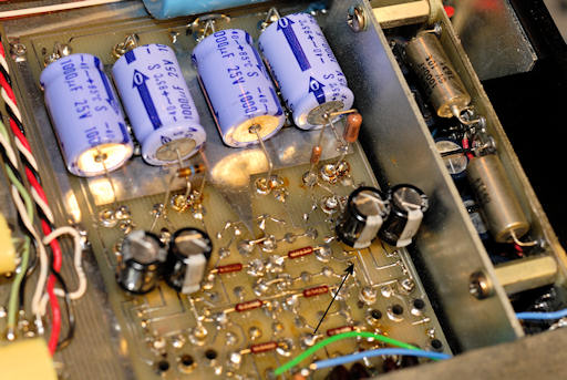
The 4 black 220 μF 25 volt caps replace the 4 150 μF 6 volt tantalums. Note the marked cap is reversed in polarity compared to the original. These caps typically operate near zero volts, but the offsets of the modules can be opposite of what's expected. Check the actual voltages across the caps to be sure they don't see reverse voltage! This would have been very bad for the original tantalum caps because even if they don't fail, tantalums generate a huge amount of noise if reverse biased.
The stand-up resistors are used to adjust the output offset of the RIAA modules per the instructions on the schematic. They should be between 1.8 and 22 megohms. One of mine needed to be 1.3 megohms and this may account for the reverse bias on the capacitor since changing the input bias changes the voltage on the caps. As far as I can tell, that's how the factory shipped it, though I did replace the resistor with metal films when checking it. For goodness sakes dress your resistors better than I did- I need to go back and clean that mess up, but don't make them hard to change. You can measure the output offset of the RIAA modules on the 5 μF film capacitors on the top of the board. These caps are to the far right near the front panel. The signal is on the end of the caps closest to the RIAA section. Try to get the offset under a couple hundred millivolts and note that there's a certain warm up time before it stabilizes.
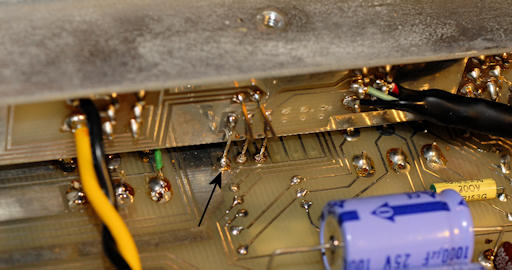
This pin provides the ground for the controls, the volume control in particular. If the connection is broken, the volume control is no longer a divider and the preamp will go to full volume, possibly destroying your speakers and/or amplifier. It may not be common, but it happened to mine on the bench, not in the system thank goodness, probably from the slight flexing of the PCB while changing caps. Another unit I worked on had two similar ground failures. The pins may not actually protrude through the board and are problematic. The cracks in the solder joints are difficult to see so it would be wise to resolder all the pins, regardless of appearance.
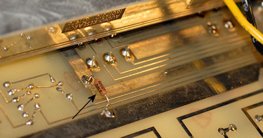
The idea of a ground failure on the volume pot was too much for me to accept. Here a 10 kΩ resistor has been installed between a reliable ground and the volume pot ground. This has basically no effect and does not mess up the grounding scheme used by ARC, but if the above ground pin fails, this resistor will keep the volume under control. You'll also know that something is amiss because the volume will be at about 10% even with the control set all the way down. I sleep better at night with this resistor in place.
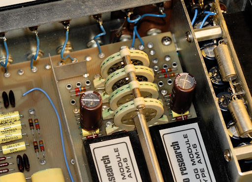
The RIAA phono inputs pass through two 150 μF 6 volt tantalum caps installed over other circuitry. Though I've no proof, the use of tantalum caps in this location seems very risky to sound quality. This is the only place where I've used an "audio" cap, a pair of 220 uF 35 volt Silmic IIs. Again, the reason for using a higher voltage cap is for the lower dissipation factor and good linearity, even though it only sees a few volts in operation. Like the other locations, even a large radial cap fits perfectly here. →See the RIAA section for latest mods. The large value electrolytic was replaced with a moderate value film cap.
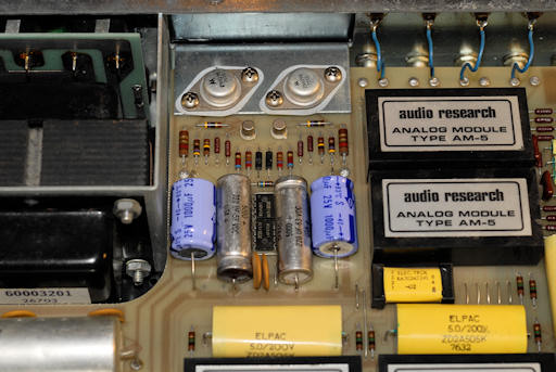
You'll need to change the four voltage regulator caps. The two on the outside are the same 1000 μF 25 volt parts used on the bottom of the board. The two on the inside were 140 μF 50 volt parts, a somewhat odd choice. The operating voltage is 15 volts so 25 volt caps should be entirely sufficient. They may have chosen 50 volt parts to get better esr as the caps filter noise from some zener diodes. I used 220/63 parts because I had them in stock. Try to find a suitable axial type as a radial would be a poor fit here. Watch your polarities!
I haven't changed the main power supply caps yet as they measured OK. Not great, but they have some time left. A change is definitely in the future. Note that the two large electrolytics mounted on bottom of the board were added by ARC for the SP-4A version. In fact, as far as I can tell, that's the only real difference between the 4 and the 4A. Why they decided that an extra 5000 μF was needed on the output of a regulated supply for a preamp is beyond me. My unit is marked SP-4 on the front panel, but has a factory applied sticker on the inside edge of the front panel marked SP-4A.
While you're in there, and if your controls are noisy, give them a shot of DeOxit. The controls have a small slot on top where you can direct the spray. You'll need to bend the end of the red tube extension to access the hole under the front chassis lip. Try a bit of heat and maybe cutting the tube at an angle. You have to direct the spray down and even back towards you a bit for it to be effective. My right channel volume pot was quite noisy and the DeOxit did a good job of quieting it after two applications and multiple knob rotations.
For a few dollars more you could replace the various yellow Mylar caps with polypropylene. There are also various carbon composition resistors in the signal path that should be replaced with metal film. The silver-mica caps are probably OK but a true purist would replace those with close tolerance matched polystyrene or polypropylene.
I'll also mention that the input connections of the main amplifier modules don't quite match the schematic on my unit. There are two 2.7 kΩ resistors soldered in series with each of the Mylar caps on the bottom of the board. I haven't traced it out entirely but be aware that some details are different and may vary unit to unit.
The rear panel and AC related parts appear to have been built up such that disassembly is nearly impossible. Maybe there's a trick to it, but I'd avoid trying to service the fuse holder and outlets at all costs.
The muting relay (K1) should be trouble-free, but for documentation purposes it's an Elec-trol RA30342241-02 (DPST) with a coil resistance of 1718 Ω. The construction is the usual dual glass tube reed assembly, however there's a copper foil electrostatic shield around the tubes connected to the pin marked "E". The coil is between pins 1 and 2. The operating voltage is about 25.1 VDC, giving a power dissipation of 0.367 watts. There are various reed and DIP relays that could be subsituted, though few if any with the same pinout and spacing.
Before the changes the best description of the sound might have been dead, lifeless and a bit bass shy. After the changes I'd say the sound is full, lush and has a rich and detailed bottom end. Don't you love audiophile descriptions of sound quality? I don't think it's quite as defined as my more modern LME opamp based preamp, but it's definitely pleasing. I attribute most of the improvement to just eliminating the tantalum caps from what are probably critical circuit areas. It's a bit frustrating because one can't tell if a cap is used for simple supply bypassing, or is setting a low frequency breakpoint on a feedback network.
The following table gives the measured capacitance and dissipation factor for all the removed capacitors, plus a brief description of what I installed in its place. This may help in parts selection and gives an idea of how much (or little) degradation is to be expected in 37 year old aluminum electrolytics. As a point of reference, a garden variety 1000 μF 25 volt cap might have a published maximum dissipation factor of 0.14 and the end of life would be 2X that. Thus, 0.28 would be a good point to think about replacement. By that standard most of the caps here are in reasonably good condition and even the ones with higher dissipation probably aren't causing any obvious circuit problems. The one tantalum with high leakage is a bit odd and I didn't keep track of what caps came from where, but I'd guess it was the one with a small reverse bias in the RIAA section.
All the leakage numbers were for full rated voltage and would have come down even further if I had waited more than a few minutes. None of the replacement capacitors would do nearly as well since it takes many hours of operation under voltage to develop the lowest leakage. Though I don't believe in weeks of "break-in" for capacitors, the lowest leakage isn't achieved for some hours of operation. It's also interesting to note that many of these capacitors have operated far below their rated voltage for 37 years, yet when tested for value and leakage at full rated voltage none had any problems with de-forming, breakdown or leakage.
| Value | Voltage | Cs120 | DF120 | Leakage, uA | In Spec | Replacement | Comments |
|---|---|---|---|---|---|---|---|
| 1000 | 25 | 1070 | .090 | 15 | yes | 1000/25 | Panasonic, no type |
| 1000 | 25 | 1130 | .093 | 15 | yes | 1000/25 | |
| 1000 | 25 | 1120 | .079 | 15 | yes | 1000/25 | |
| 1000 | 25 | 1150 | .103 | 10 | yes | 1000/25 | |
| 1000 | 25 | 1550 | .16 | 20 | ? | 1000/25 | |
| 1000 | 25 | 1070 | .11 | 20 | yes | 1000/25 | |
| 1000 | 25 | 1140 | .11 | 10 | yes | 1000/25 | |
| 1000 | 25 | 1090 | .095 | 10 | yes | 1000/25 | |
| 1000 | 25 | 1080 | .12 | 10 | yes | 1000/25 | |
| 1000 | 25 | 1120 | .098 | 10 | yes | 1000/25 | |
| 2800 | 6 | 2600 | .22 | 15 | yes | 3300/16 | Panasonic FC |
| 2800 | 6 | 3070 | .20 | 25 | yes | 3300/16 | |
| 2800 | 6 | 3040 | .36 | 25 | yes | 3300/16 | |
| 2800 | 6 | 2270 | .21 | 10 | yes | 3300/16 | |
| 2800 | 6 | 2420 | .22 | 15 | yes | 3300/16 | |
| 2800 | 6 | 2420 | .37 | 25 | yes | 3300/16 | |
| 140 | 40 | 212 | .07 | 15 | ? | 220/63 | Sprague 500D |
| 140 | 40 | 182 | .06 | 10 | yes | 220/63 | |
| 150 (T) | 6 | 150 | .021 | 2 | 220/35 | SilmicII for RIAA inputs | |
| 150 (T) | 6 | 147 | .025 | 4 | 220/35 | ||
| 150 (T) | 6 | 141 | .034 | 2 | 220/35 | Rubycon YXF | |
| 150 (T) | 6 | 150 | .021 | 2 | 220/35 | ||
| 150 (T) | 6 | 144 | .022 | 2 | 220/35 | ||
| 150 (T) | 6 | 142 | .031 | 28 | 220/35 | high leakage | |
| 330 (T) | 6 | 310 | .038 | 2 | 330/35 | United Chemicon SXE | |
| 330 (T) | 6 | 310 | .048 | 2 | 330/35 | ||
| 330 (T) | 6 | 318 | .028 | 2 | 330/35 | ||
| 330 (T) | 6 | 303 | .036 | 3 | 330/35 |
C. Hoffman
last major edit May 30, 2013
Followup Notes:
11/27/16 My volume control has never been silent and no amount of DeOxit has helped for more than a few days. I suspect it has been
the cause of random channel balance problems. It's extremely hard to service and exact replacements are unavailable. This is a preamp
I long to love, the cosmetics are great, but everything else about the construction, circuits and reliability is problematic. Since
sound quality is my real obsession, it's once again being pulled from the system in favor of other preamps.