Many people have reported hum problems with the Sansui 881 receiver. Minimal hum requires that the various screws that ground the circuit boards to the chassis be clean and tight. Naturally the circuitry needs to be functioning correctly and this may require replacing capacitors, cleaning controls and all the usual service necessary for a receiver of this vintage. This may be sufficient to reduce whatever hum is present to inaudibility, at least for your particular speakers and listening conditions. If that does the trick, for the love of dog stop reading right here. Go play some tunes. Seriously, this is a case of what you don't know isn't going to hurt you. If you keep reading you'll be infected with an incurable case of FUD (fear, uncertainty & doubt). You've been warned.
OK, so audio OCD has forced you to keep reading. As much as we all love and respect Sansui, they really blew it with the 881 power supply board and amp board layout. After the circuit design was done, they probably passed the layout job down to some junior engineer who had yet to pass power supply design 101. Whatever happened, nobody with grounding experience checked the work and noticed the problems.
Keeping hum out of audio circuits requires that no ground connection be made within the loops where filter capacitor charging currents flow. The brief high current pulses there develop significant voltages even across short trace lengths. A half an inch error in connection locations can make the difference between silence and hum. Further, local bypass caps can't have their ground lines returned to local signal grounds, lest the normal power supply ripple be coupled into what should be a "quiet" ground system. All traces and wires have resistance, so unwanted ripple currents translate into voltages that can get amplified and become hum. Ideally, a single point ground is used for sensitive analog circuits to be sure everything is operating at the same potential.
People sometimes resort to heavy gage wire, wide traces and extra heavy copper to fight hum, but it's a losing battle. Unwanted voltages, though less, are still generated. When the ripple currents above are properly routed away from sensitive circuitry, wire and trace resistance become of much less concern.
In the case of the 881, grounds were tied where convenient to the layout person, not at the locations necessary to give minimum hum. It appears they then tried to correct the resulting hum problems after the fact, by soldering multiple ground wires to particular locations on signal board traces, hoping to balance or cancel the hum. It didn't work. Though the hum levels can be fairly low, some small amount of hum is almost certain to be heard through headphones or if you put your ear close to a speaker. Just as bad, though not as obvious, as the power level increases, the ripple on the power supply increases, and thus the amount injected into the signal increases. Though I can't say it's audible, it certainly isn't desirable.
After struggling for a couple weeks, I had my doubts. The layout department sabotaged this model about as thoroughly as they possibly could. Finally, the last error revealed itself, and I can now say it's possible to have an 881 that's 100% free of hum, or at least whatever hum remains will be buried far enough below the noise so as to be undetectable.
The fix isn't for the faint of heart, the owner who values originality over all else, or the electronic neophyte who hasn't done this type of rework, but it isn't terribly difficult or time consuming. You have to decide if you want a hum-free receiver, or if the idea of cuts, jumpers and parts mounted with a single lead is too horrible, and the small amount of hum is tolerable. There's nothing wrong with either answer. If you're experienced with this sort of thing, it can be done in under a couple hours. Be sure to read the entire fix several times before beginning, preferably with the unit open in front of you. It may be that less than the entire mod is sufficient to your needs.
The changes below are designed to isolate traces where 120 Hz (100 Hz if you're over the pond) capacitor current pulses flow, and get most of the analog grounds rerouted to a quiet single point ground. There are two benefits to this. First, we eliminate hum generated within the unit. Second, by removing hum currents from the ground and chassis system, we prevent strange interactions with other components grounding systems.
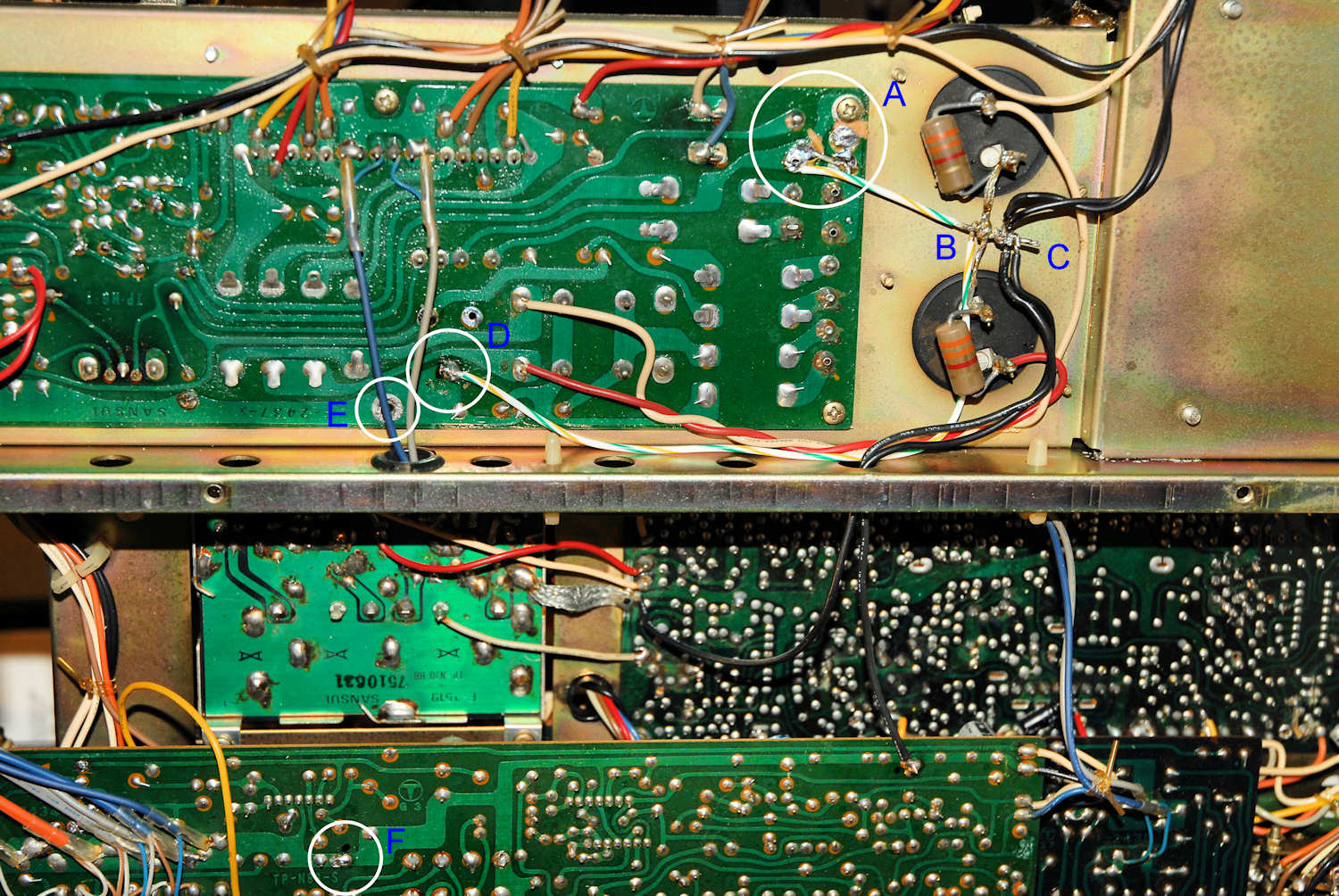
Alas, I neglected to take photos of the original grounding scheme, but the following photo shows what was necessary to correct it on the power supply board. There is an additional change to the power supply board not shown in this photo, but it will be shown in a moment. Finally, the last key to the puzzle, residing on the amplifier board, will be described. Have fun & good luck.

A- This is the point where transformer center taps tie to a chassis ground screw and then go on to the filter cap ground. No signal grounds, or the chassis, should ever be connected here. The tuner board and other low level circuitry connects to the chassis, so injecting AC cap charging currents into the chassis is a recipe for hum. There are at least two slightly different power supply board layouts, so it's important to look carefully at what you've got. In this case, two trace cuts are necessary. Use a medium burr in a Moto-Tool and brush gently across the traces to disconnect the mounting screw from the circuit. Go just deep enough to remove the copper and expose the light brown of the circuit board. There are no prizes for digging deep trenches. There will have been a solder lug here, so remove that, and the screw, for access. Scrape the ends of the traces clean of green solder mask with a slightly curved blade, or a straight blade held at a low angle so you can solder them in the next step. Put the screw back. The screw is not to touch any traces other than its own little isolated pad that you just created- it just holds the board in place now.
B & C- The two traces above are connected together at one end of a wire and then are connected to the filter caps by making one wrap around the cross braid and leaving a stub (C) to the right. We're keeping the braid connecting the two filter caps, but are adopting a new philosophy. Transformer charging currents will come in from the left and tie to the center of the braid. That path will be the "dirty" power supply return. The stub (C) is brought off to the right as described above. This stub will be declared the "clean" single point signal ground. In the above photo, the wire to the traces loops back to catch the other trace, but I later cleaned this up as shown here.
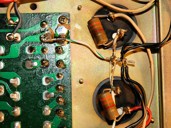
When you have the dirty ground on the left and the stub on the right, point to a spot a couple millimeters down the stub with a hot soldering iron and recite the following:
"I hereby declare that this point shall be the one true ground. One ground to rule them all. One ground to define them. One ground to bring them all, and in the darkness bind them. One ground, by definition, to be ever at zero volts AC and DC, electrically quiet, for time and all eternity."
That should frighten the demons of hum sufficiently to insure the success of the mod.
D & E- This is a change from the first draft of this page. The trace is the ground trace for the 1000 uF cap (C04). The charging currents here are high, so this is a rather dirty ground. Initially I simply removed the chassis screw and ran a ground to the dirty ground point. The problem with that is the regulated supplies also use this trace for ground. A better solution is to cut the trace in half and ground each half separately. The dirty ground of C04 is left as shown in the first photo, with the striped wire heading off to the dirty ground at the filter caps, but we'll add a cut as shown here.
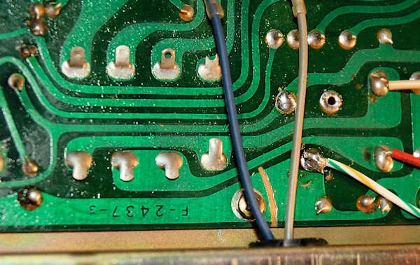
Now half the trace has no ground connection, so we have to provide one. I tried running a ground wire to the clean ground, but the result was exactly the same as just using the chassis screw and star washer. Since that's easier and we still need to hold the board in place, I went with the screw. It isn't as textbook as the wire, but in this case it doesn't appear to make a bit of difference.
We now have a reasonably good ground system and can start connecting circuitry to the quiet ground at C. There will be two black wires- the speaker returns. There is a third black wire, tied to a white one, that goes to the relay- you don't want that one. You can check continuity between the disconnected wires and the black speaker terminals to confirm you've got the right ones. Solder these wires to the stub (C) near, but not at, the cross braid.
Remove the ground wire that goes to point F. You don't need it and it connects the same trace as the ground wire to the right. Unsolder both ends and discard it. Connect the other wire to the stub (C) just to the right of the speaker return wires.
Connect the ground wire from the tuner board (at the large braid) to the stub (C) next.
Check your work and compare it to the photo. Use an ohm meter to confirm that both traces near the screw on the power supply board are connected together and connected to the filter cap common at B. Check for continuity from the negative lead of the 1000 uF cap to B. Check for continuity between the chassis and circuit grounds. Check the tightness of all screws holding all boards to the chassis.
Power up and listen for the relay to close in about 1 3/4 seconds. Hopefully all is well, the hum has been reduced somewhat, but likely isn't completely gone.
This is where things get a little less elegant than I'd like, but there's no getting around it. The power amp board has an RC filter on the positive supply line of each channel. It consists of the 100 ohm resistors R29 and R30. Those are followed by 100 uF filter caps C11 and C12. There will always be significant ripple on the supply line, increasing as you turn up the volume. C11 and C12 filter the voltage to the input stage of the power amp, but that ripple current through the caps has to go to ground. It must never go through signal ground, or it will cause hum. It has to go back to the single point ground at the main caps. The problem? The power amp board only has signal ground present. There's no way to go through the edge connector and get to a suitable (dirty) ground.
To fix this, install new caps for C11 and C12, inserting the positive leads in the board, but bend the negative leads 180 degrees so they point up in the air. Fasten the leads together with insulated wire, with a bare section in the middle. The best way is to simply twist two pieces together so you have a nice connection point in the middle. You need this easy to solder and unsolder connection point so you can get the amp board in and out of the chassis for service.
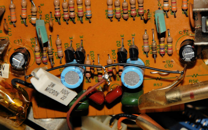
Now run a wire from the single point ground, right at the braid, to the top side. Use any convenient hole or path available. I had previously replaced the 1000 uF cap on the power supply board (three leads) with a new two lead part. That left a handy hole to run the wire up. Make a loop in the end and solder it to the center of the cap ground wire. Don't crimp it, but make it easy to remove and reattach, if and when needed.
I was going for a full grounding fix and used very sensitive means, the THD analyzer residual and a very high gain differential scope plug-in, to determine when the goal had been reached. But, I didn't compare the contributions of the various grounding errors alone. The RC filter cap grounding seems to be a major part of the problem, so if the full mod is putting you off a bit, you might want to try that simple (and cut free) part of the mod first.
Finally, there are four 3.3 uF caps on the supply lines of the power supply board, the local bypass caps. They have the same issue with their grounds, dumping into the quiet signal ground. These can be replaced, but put them sideways on the bottom of the board, with the leads previously going to the ground trace, pointing up in the air. Tie them together and connect to the dirty ground right at the cross braid. Be very careful to get the polarity right or bad things will happen. Don't forget to trim off the leads on the top side of the board! You can also increase them to 22 or 47 uF if desired.
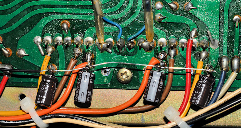
While you're working on the 881, and if it hasn't been done before, install a new electrolytic cap at C11 (47 uF/50V). This is the filter for the supply that runs the relay. It's fed from a single half wave rectifier so it sees significant ripple current whenever the unit is on. Because of that, the cap tends to fail earlier than others, causing the relay voltage to be low. The relay may then fail to pull in every time, or the contacts may become pitted and unreliable because they don't close with sufficient force.
The power amp board has about 8 fusible resistors that tend to go open or out of tolerance. Replace all of them. What to use is open to debate. Metal films will be reliable but if something fails they provide almost no protection and you might lose traces or have more severe damage than if carbon films were used. A search of audio forums may provide more guidance on best practice. I tend to use metal films, spaced off the board by about 0.2".
I'm not convinced that the power stage is 100% thermally stable. If you get the main heat sink quite hot on the test bench, it may be necessary to shut off the unit before it will cool off. If the temperature continues to rise with no signal present, destruction of the power amp will soon follow. This probably isn't an issue with music signals. It may be desirable to move the Vbe multiplier transistors to the main heat sink, but I haven't investigated this.
Finally, the low level board is quite noisy, probably due to the BA312 devices. It might be improved with more modern semiconductors if they could be fitted in, but I don't think a standard adapter will work because the SIL ICs aren't opamps in the usual sense, and don't have a compatible pinout. Hint- you can use the -20 dB button to reduce the noise when using headphones, just don't accidently push it again and wreck your hearing or your headphones. Never leave headphones plugged in during normal listening with the speakers.
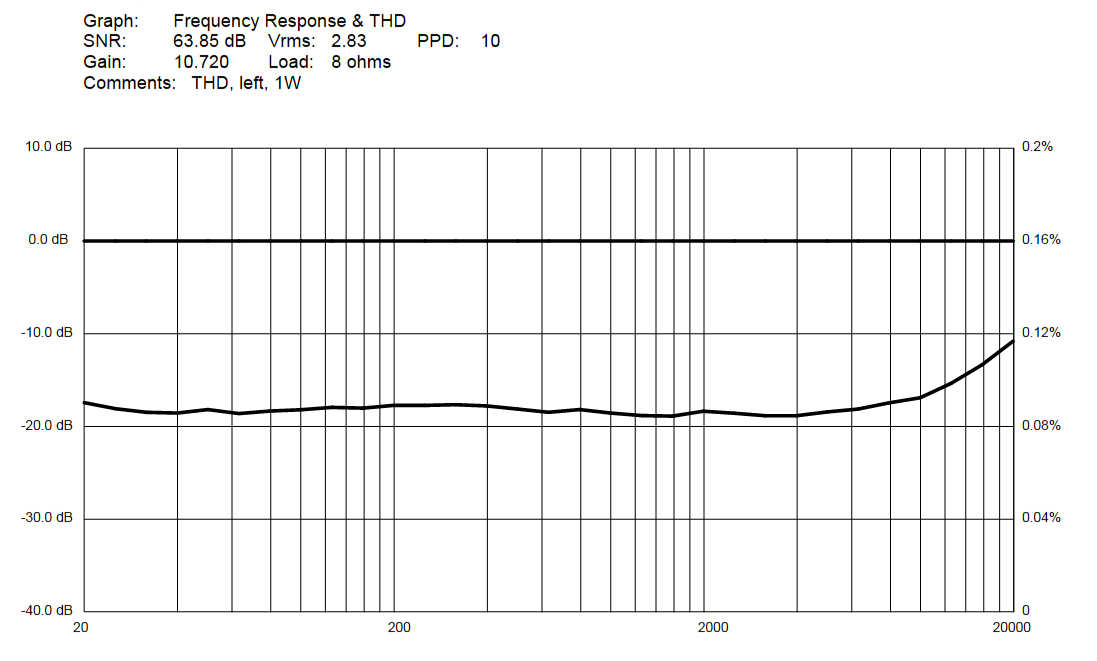
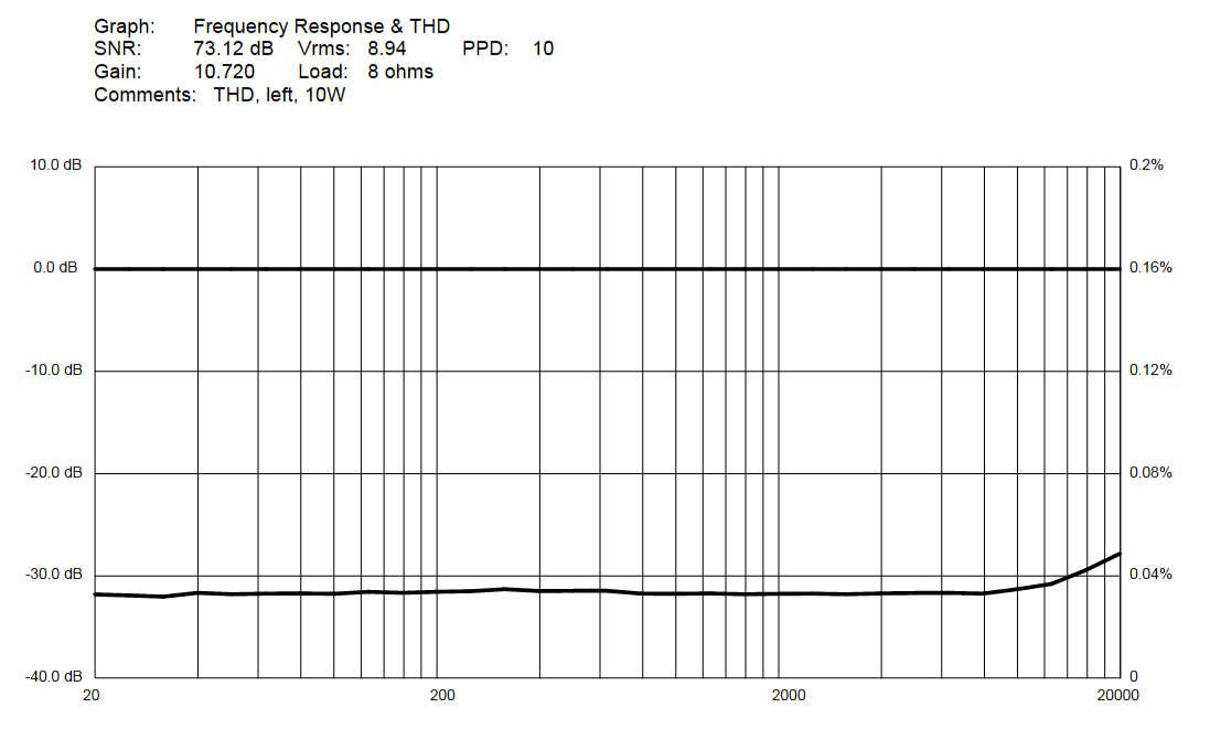
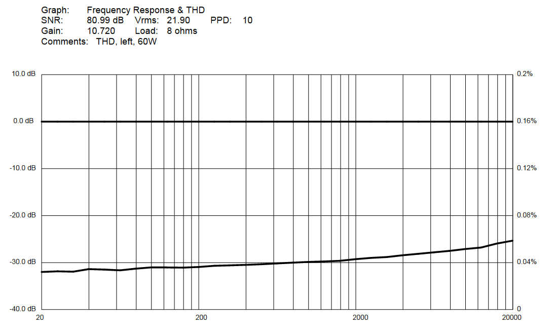
Looking at the THD residual on the scope, no actual distortion was visible until higher frequencies, just a big hum component, plus some noise. After the mods, there was no hum signal riding on the residual at all. Zip, zero, nada. At low frequencies whatever distortion was present was buried in the noise. At high frequencies and at higher powers some 2nd harmonic rises up out of the muck. The Sansui THD spec doesn't specify the measurement conditions, just a flat number of 0.3%, which is quite a lot. Here are curves for 1W, 10W and 60W. The performance is way better than the published spec, in fact most of what you're seeing is still just noise, not THD. What you're not seeing is hum! The frequency response is flat, but these graphs are a bit too perfect in that department because I didn't run the response sweeps- the software defaults to a flat line with no data. Though the noise level is fairly high, the unit does meet the published 70 dB number if the gain setting is chosen wisely (low enough that the tone board noise doesn't dominate) and the measurement is made at a few watts or higher.
I've only worked on a single 881, so if you do this mod please report back on your results and if the process was clear and easy to follow, also if it seemed to match your particular unit. The 881 I worked on differed from the service manual a bit- the tuner board was the more complex board found in the 9090, the manual for which also has the correct alignment instructions. The power amp board didn't quite match the schematic. My guess is that Sansui tried various approaches to getting rid of the hum, so there may be more than a couple variations on the boards and wiring. It would also explain differing reports on how much hum these units have.
C. Hoffman
last major edit January 10, 2016