A Compendium of Tests & Measurements
for the
B&W Darkroom
Photography has been my hobby for several decades, but I make my living designing scientific instruments. Precision test and measurement figures prominently in that endeavor, so it was natural to apply the same techniques to my darkroom work.
It would be nice if all our darkroom equipment were built to the highest attainable standards, but the laws of economics dictate otherwise. Manufacturers can only pursue perfection so far, then they have to trade off accuracy and precision to offer competitive prices in a relatively small market. It isnt some evil plot to complicate our lives, but simple economic necessity.
That said, our goal is to apply precision measurement techniques to ferret out weaknesses in our equipment, and take corrective action.
Before we get down to business, and if you dont already, I suggest you keep a darkroom notebook. I use a clipboard hanging from the wall and jot down the date, the particulars of all film processed, and enough information to duplicate prints I feel good about. You dont have to go crazy with data collection, but a consistently kept notebook will show you trends you might otherwise miss. It will help you make changes in a methodical fashion. Naturally you should devote a page to the tests below. If the performance of some item is later questioned, its an easy matter to retest it and compare the results with the original data.
Volume Measurements
Photographic processing depends on accurate measurement of volume, yet we typically assume that photographic graduates are accurate with no testing or verification. We also assume stability over time- that plastic graduates dont shrink or change shape as they age.
My experience with photographic graduates has been quite poor, but I also tend to buy on sale and at flea markets. OK, I got what I paid for. Not only were my molded glass and plastic graduates in error, but I also found the markings on laboratory beakers to be rough estimates at best. Since photographic processing is a complex system, choosing a single acceptable error band for liquid measurements is difficult. Im comfortable with plus or minus five percent, but there are times when this is overkill, and times when you may need to do better. For the vast majority of mixing tasks I believe its a reasonable number.
To check your working graduates, you need an accurate reference graduate for comparison. A lab type graduated cylinder that conforms to ASTM standards at 20° C is a good place to start. 250 ml is a handy size, and some sources are listed at the end of the article.
Carefully fill your reference graduate with water, reading the lower edge of the slightly curved liquid surface (meniscus). Naturally the graduate should be resting on a level surface. Transfer the water to your working graduates as many times as necessary. Check your working graduates at the minimum, maximum, and a few places in the middle. Retire the ones you cant live with, and check the plastic ones periodically, as they may change over time.
If you have a good scale, you can also check volume by weight. 1 liter of water weighs exactly 1 kilogram. 1 U.S. fluid ounce weighs 29.57 grams, and 1 quart weighs 946.35 grams. Dont forget to subtract the weight of the graduate itself (tare) from the measurement. An ordinary 2 kg chemical balance can resolve about .1 g, or .1% of 100 ml of water, quite a bit better than needed.
Temperature Measurements
Its often argued that consistency in temperature measurement is all that matters, since youll adjust your processing time for the results you want. I disagree. Without accuracy, you cant have a meaningful dialog with others, at least with regard to processing. You may also decide that manufacturers process recommendations are inaccurate, when the real problem is your inability to follow them. Manufacturers test carefully. When their recommendations dont work well, I immediately suspect a process problem. More often than not, Ive made an error in time, temperature, or agitation. Or I wanted a different contrast index than the recommendation was designed for. Yes, those numbers are a starting point, but a much better one than often given credit for.
There's an even more important reason to calibrate your thermometer. What if it's significantly in error, and you break it? All your process calibration is now lost, with no easy means of recovery. If you had a perfectly functioning zone system, its gone. On the other hand, if youve performed the tests below, you simply buy another thermometer, calibrate it, and get on with business as usual.
There are many well researched temperature calibration points. These include the triple point of water (.01° C), and the freezing point of various metals, such as tin (231.913° C). Unfortunately none of these very stable reference points occur near our process temperatures, not to mention the difficulty of using them. Fortunately, we dont need true calibration lab accuracy. ± ¼° F is more than adequate for all but a few color processes, and we can achieve that through careful comparison with a good lab thermometer. See the source list at the end of the article.
Good high resolution thermometers generally contain mercury, so use extreme care not to drop or overheat them, risking breakage. Mercury vapor is poisonous, and will penetrate most materials, including photographic packaging. Its a powerful photographic sensitizer, and will alter the characteristics of any paper or film it comes in contact with. If spilt, it is nearly impossible to recapture the microscopic droplets. Do not use mercury thermometers as your working thermometers in the darkroom!
Use a stirred water bath to minimize any temperature gradient between the two thermometers. Compare them at your normal process temperatures, plus ten degrees or so on either side. Keep your reference thermometer safely stored away except when testing working thermometers; that should be its only purpose. If you dont want to invest in a good reference thermometer, you can still check your working thermometers with more commonly available items.
The average dial thermometer covers 25° F to 125° F. You can check the lower end with a well stirred mixture of water and chopped ice. Ideally these should both be made from distilled water. The reading should be 32° F after a few minutes. The upper end can be checked against a standard fever thermometer. These typically read from 96° F to 106° F with very good accuracy. Remember that the fever thermometer is designed to hold its highest reading until you shake it down, unless it's digital. Use a large water bath so the temperature doesnt change rapidly. You can be reasonably certain that a working thermometer accurate at 32° and say, 97° will also be good at 70° .
Record the readings in your darkroom notebook for future reference. If the error is significant, apply the appropriate correction factor in future work.
If youre checking dial thermometers, reject any that make sudden jumps up or down. Id also be wary of thermometers having condensation inside the window. Check them frequently or replace them. Some of the larger process thermometers can be adjusted by removing the cover and shifting the pointer slightly while holding the stem with a screwdriver. Others have an adjustment screw on the back. Smaller dial thermometers typically arent adjustable by the user.
Dimensional Measurements
Paper trimmers are notorious for having inaccurate scales. Get a steel machinists rule and check the trimmer scale for correct overall length and division, then check several pieces of freshly cut paper. Shift or replace the trimmer scale as necessary. Some enlargers have scales for the vertical position that can be adjusted. These are the only distance scales I use in my darkroom, but if you have others, check them too.
Time Measurements
Good metrology practice requires that you check everything that affects your process. Modern timers are extremely accurate, but we still have to go through the exercise of checking them. Compare your timers against a digital watch of known accuracy. (A watch that gains or loses a minute per week is still good to .01%.)
Mechanical Measurements I- Enlarger Vibration & Damping
Your enlarger will vibrate at its natural frequency if excited by an energy source. Changing negatives and focusing are the biggest disturbance, though building vibrations can cause problems if your darkroom is on an upper floor. Damping determines how quickly the vibration dies out, after removal of the outside energy source.
The usual arrangement where the lamphouse is cantilevered out over the baseboard isnt very good for rigidity or damping. Surprisingly, most columns are pretty good. The problem is often the baseboard or the column attachment. With only front and rear feet, the baseboard tends to flex in the middle, allowing the head to vibrate to and fro. Over time, the baseboard will also warp from the constant pressure. A couple pieces of aluminum angle screwed to each side of the baseboard can work wonders, as can a central foot. If the column-to-baseboard attachment isn't rigid enough, a top brace to the wall may help.
The parameter we need to measure is the settling time of the enlarger, the length of time you have to wait before starting an exposure. We can do the job with just a grain focuser and a stopwatch. Any negative will work, but I prefer much higher contrast. A film leader with some "X" scratches through the emulsion is best. Place the enlarger head at your normal height or a bit higher, then focus on the scratches with the grain focuser.
Now, "ping" the head or column lightly with your finger and watch the motion of the scratches. Record the time it takes to completely stop vibrating. This is the amount of time you must allow after touching the enlarger, or closing the easel, before starting an exposure. You can also use this method to check the efficacy of any improvements you make. For reference, my Beseler 23CII settles about 1.5 seconds after receiving a moderate bump. That isnt a long time, but its still easy to hit the expose button too soon if youre in a hurry.
The Enlarger Optical System
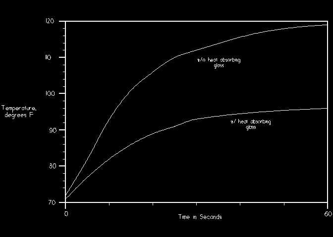
You cant get sharp prints if the negative moves during the exposure. Negative "pop" is simply a slight buckling that occurs as the negative heats up due to radiation from the enlarger lamp. To give you an idea of how much heat can be present, I attached a small thermocouple to the top of a dense negative. I then timed the temperature rise with and without heat absorbing glass (Beseler part #8042). The results are plotted below (click to enlarge).
Special "heat carrying" properties have often been attached to infrared radiation, however thats complete nonsense. Most of the radiation from an incandescent lamp resides in the infrared, with only a small portion falling in the visible spectrum. Blocking the infrared eliminates most of the lamps radiated energy, thus there is much less total energy impinging on the negative. Heating depends on the absorption at each wavelength, but not the wavelength itself.
These measurements should convince you that heat absorbing glass is an essential item. The usual variety of this glass will cut the negative temperature nearly in half. Filters that limit the temperature rise to only a degree or two are also available, but the cost is an order of magnitude higher.
The next test is for evenness of illumination. Traditionally, an empty negative carrier was imaged onto a piece of paper, and the exposure adjusted for a medium gray tone. Falloff or hot spots were then easy to see on the processed print. Perfectly reasonable? Not! A well known rule of testing is "Test it the way you use it."
Do this test with an evenly exposed and processed piece of film in the carrier. A density near .3 is good (light gray). Illumination problems that come into focus at the carrier will then illuminate their pattern on the film grain. The empty carrier method showed nothing wrong with my 23CII, but the film method quickly showed an area of the lamphouse that was missing some paint. A black area above the lamp was being seen by the condensers as a dark annular ring. This ring was actually visible in prints, particularly in light gray sky areas. A few minutes applying some white paint solved most of the problem. (Newer models shouldnt have this problem, as the lamp carrier has been redesigned.)
At the same time that you do the above test, check for vignetting at the corners of the frame. Light corners detract tremendously from an image, as they tend to lead the eye out of the frame.
Complete your examination of the optical system by looking for contrast reducing reflective areas. Everything inside the bellows should be flat black. Check the back of the lensboard, and the underside of the negative carrier. Paint as required, but leave the lens off and the carrier slot open until the paint is completely dry.
Mechanical Measurements II- Enlarger Alignment
There are really just two requirements. First, the baseboard, lensboard, and negative carrier, must all be parallel. Second, the central axis of the lens, negative carrier, and hopefully the condenser system, must coincide.
A bubble level is sometimes used, but its not a very accurate technique. The condensers and/or lamphouse often have to be removed to see the level, and that changes the loading on the frame and baseboard. What looked like perfect alignment is lost when the enlarger is reassembled. If you must use that method, try to keep the enlarger assembled. Place the level on the baseboard and shim the feet with paper or cardboard until the bubble is perfectly centered. Move the level to the lensboard and negative carrier; adjust them until level. It may be convenient to put a flat piece of glass in the carrier location, and keep the level outside the enlarger. Be sure to check both directions if you are using a regular level, rather than a circular level. A machinists level will give a far more accurate result than the typical woodworkers level, however the money might be better invested in one of the proprietary alignment tools.
There is a simple and far more accurate method of alignment that uses two mirrors, one with a small hole (approximately 1/8" diameter) drilled through it near one edge. The mirror with the hole is installed in place of the negative carrier, with the hole outside the enlarger in a position such that you can look through it. The other mirror is placed on the baseboard, directly under the hole. Look through the hole. If the two mirrors are perfectly parallel, you will see what looks like a single hole. Any misalignment will result in a "tail", or even a row of holes. The drilled mirror is held against the lower lip of the enlarging lens to check the lens stage in the same way. If the hole is hard to see, make a target around it with some thin white tape and direct a small lamp up towards it. See the source list for a suitable glass drill.
You will be at the mercy of whatever adjustments are present, some of which may move several things at once. If something is out of whack, and there isnt any adjustment, you may be able to shim it using paper or foil. You can also make friends with a machinist (unless you didnt return the level you borrowed) and have the part trued up in the shop. Be careful with that method, as theres no turning back once metal is removed. Be sure spare parts are available and affordable.
Commercial alignment tools are also available and these should work extremely well if properly made.
Be careful not to lean on the worktable or the enlarger baseboard while testing, as alignments may shift slightly. Also check that the vertical locking mechanism doesnt affect the alignment as its tightened. It's common to have variations in baseboard flatness, and even the carrier stage, that are easily seen with the level or mirrors. To avoid chasing alignment issues forever, standardize on one place to make your measurements and remember that the parallel mirror method is extremely sensitive.
You should next confirm that the lens and negative are on the same axis. I use a special plug for this with a diameter of 1.7", the diagonal dimension of a 35mm frame. The bottom just fits in the lensboard hole. The idea is to bring the plug up to the lower surface of the negative carrier, looking for equal spaces at each corner of the opening. Often something as simple as a plastic film can slipped over the rear of the lens, or even a carefully made paper cylinder, will serve as well.
Accessories
Darkroom workers place unwarranted trust in the accuracy of grain focusers. There are many pitfalls in the use of these devices, as described by Ctein and Gainer. Even without errors due to the spectral sensitivity of the paper and LCA, how do you know the grain focuser itself is correctly adjusted? In principal, its a simple device, requiring only equal path lengths from the base and reticle, to the mirror. All it really does is redirect the image to a more convenient location, and allows us to view the aerial image at sufficient magnification to see the grain. Note that some project to a ground glass screen, rather than using the aerial image. These won't be as bright, but suffer from fewer error sources.
First, lets weed out the cheap sheet metal imports built with incorrect mirror angles. Look straight down into the mirror. You should see the reticle, and probably the upper eyepiece body, centered in the mirror. If you have to move your head off at an angle to see the reticle, invest in a better focuser. Another tip-off is that the bright area isnt centered when the focuser is centered under the enlarger. Place the focuser on a flat surface and be sure it doesnt rock or wobble.
Since a grain focuser is designed with high magnification to show small focus differences, we need something with equal or better focus resolution to test it. Lacking a well equipped optical bench, the following procedure is a close second.
Install a macro lens (or some extension tubes) on your SLR and mount it on a copy stand or tripod. Level carefully. Hint- use the drilled mirror method described for enlargers. Place a sheet of paper with some crisp text under the setup and focus on it, leaving enough room between the lens and the paper to set the grain focuser. The more magnification you can achieve, the better. When you slide in the grain focuser, the reticle should become visible in the SLR viewfinder, and be at the exact same focus as the text was. Shine a bit of light down the focuser eyepiece, if necessary, to illuminate the reticle. Adjust the reticle position (if possible) until the reticle and text are at the exact same focus.
This method works because the test setup has almost no depth of field, making focus discrepancies between the base and the reticle much more obvious. Carefully done, it can resolve a focus difference of well under a millimeter.
The issue of focus error due paper thickness sometimes comes up, but it's of little consequence. The fact is that you can't place the plane of sharp focus within one paper thickness with even the best focusing system, and certainly not without a glass carrier. If you can't stop thinking about it, use a water soluble glue stick to attach a piece of your favorite printing paper to the base of the focuser.
The Darkroom Optical System- Safelights & Light Leaks
Though rarely treated as such, the darkroom itself is part of the optical system. The walls should be light colored, though a dark area around the enlarger is good practice to absorb stray light from the paper surface. Light walls allow you to see with less total safelight power. I once worked in a flat black darkroom, walls, floor, and ceiling. Even with the brightest safelights it was difficult to see, the contrast was very hard on the eyes, and paper was always on the verge of fogging.
Repair any light leaks before performing the following safelight test. This test is often done incorrectly. Heres the right way to do it:
The reason for doing the test this way is that it takes a certain amount of exposure before the paper displays any visible density. Once you reach the linear portion of the D log E curve, a much smaller exposure will cause a visible change in density. Safelight tests on unexposed paper just dont tell you how your safelight affects your prints. Once again, test it the way you use it. A more advanced version of the test increases the time until visible fogging starts to occur. You then know exactly how much safety margin you have.
Whew!
Almost no darkroom survives this level of scrutiny with perfect marks. If you were one of the lucky ones, or have corrected whatever problems you discovered, your equipment should be up to any project you care to pursue.
My hope is that this exercise has increased your understanding of the tools of the craft, and encourages you never to assume, but to check. There are many areas we havent covered, including line voltage, water hardness, airborne particulates, ventilation, light levels for print inspection, and lens quality. These are within the capabilities of most workers, but beyond the scope of this article. Remember too that this is only the darkroom half of the imaging chain. Everything leading up to this point also needs testing and periodic inspections. Sharp imaging!
Suppliers (pricing may not be current)
Fisher Scientific Corp., Pittsburgh, PA, 1-800-766-7000 or
www.fishersci.com250 ml graduated cylinder, 08-557-1E, $25.85
500 ml graduated cylinder, 08-557-1F, $34.55
Thermometer, -1
°C to +51° C, 0.1° subdivisions, 15-000A, $23.50Travers Tool Co., Flushing, NY, 1-800-221-0270 or www.travers.com
12" machinists scale, 57-066-106, $8.50
6" precision level, 57-065-684, $60.50
General Surplus & Electronics, Rochester, NY- 716-338-7001 or www.gse-science-eng.com
Surplus mirrors for enlarger testing, lenses, filters, and optics- selection varies
Well stocked hardware store
Glass & Tile Drill Bit- Black & Decker #16901 (3/16") or similar
References:
Some Important Metrology Terms
Metrology is the science and practice of measurement. Accuracy, precision, and resolution are words often interchanged in common conversation, however they have very specific meanings in the world of metrology. Accuracy refers to the discrepancy between the true value and the result obtained by measurement. Precision refers to the agreement among repeated measurements of the same quantity. Resolution is the minimum increment that can be repeatedly detected or set.
This often quoted statement by Professor William Thomson, M.A., F.R.S. (1824-1907), later to become Lord Kelvin, has particular relevance to photographic science:
"I often say that when you can measure what you are speaking about, and express it in numbers, you know something about it, but when you cannot express it in numbers, your knowledge is of a meager and unsatisfactory kind; it may be the beginning of knowledge, but you have scarcely in your thoughts, advanced to the stage of science, whatever the matter may be."
Test Checklist