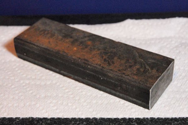
Confirming perpendicularity usually involves holding the part in question up against a common machinist's square and looking for light showing through the gap between the square and the part. For many things that's plenty good enough. Sometimes, however, you want a quantitative result, an accurate number that can be reported. Other times you may want to check the square itself for accuracy. You need a reference square, ideally one that doesn't cost an arm and a leg, and is designed in such a manner such that you can verify its squareness with common measuring tools.
A popular reference is the cylindrical square. By turning a perfect cylinder between centers, and facing the end, a highly accurate square can be produced. Some even have the base purposely cut at a slight angle, and a scale etched on the body. With that type you can measure exactly how far out of square an object might be.
It's hard to criticize the cylindrical square. The concept by which it achieves accuracy is clever and they do their job well. They do tend to be a bit expensive, motivating the home shop machinist to make their own. Ideally, they should be made on a cylindrical grinder, something few home shop machinists have or even have access to. A good job can be done on the lathe but hand work will be required as few lathes have the inherent accuracy needed to create a sufficiently taper-free cylinder. It's common to make one with two collars rather than a full cylinder, being easier to adjust two collars to the same diameter, but that's not as versatile as a full cylinder.
I'm going to suggest an alternative design, fashioned after a box square. It's really nothing more than a block of metal, with two parallel sides. The end face is adjusted for near perfect perpendicularity. Using a common indicator and stand, you can quickly and easily confirm that the square is in fact, square. If the square is a bit off, it will lean one way or the other, depending on which side you measure. Having parallel sides, perfect squareness will be exactly halfway between the two indicator readings. So in this case, even a crooked square can define perfect squareness! A surface grinder, or access to one, will make the fabrication much easier, but it's also possible to mill the device and scrape it to final accuracy.
Whenever the subject of precision angles comes up you should consider the length of the baseline involved. The longer the baseline, the larger the dimensions become and the easier it is to establish or measure angles with high precision.
As an example, imagine a carpenter's square with a 24" leg. If the square was in error by 0.1 degrees, the end of the leg would be off by 0.042", a mile in machinist speak. Consider the smallest common machinist's square, with a 2" leg. If off by 0.1 degrees, the end of the leg would be shifted by 0.0035". Small, but still easily seen and measured. Now, let's get down to real precision, say 10 arcseconds. The carpenter's square would be shifted by 0.0012". The 2" machinist's square would be shifted by a mere 0.0001". Obviously, if your going to make a reference square, it should be as large as practical. You also have to consider the size of your surface plate and the size of the work and tools you need to check.
I didn't appreciate how good a square should be until doing this project. It turns out that under the right conditions (bright light and with the eye properly lined up) you can easily see 0.001" of error (gap) between parts and a square. Probably less. With a 5" part, that's a mere 41.3 arcseconds. Thus the desire to have a reference square of 10 arcseconds or better.
In a perfect world, or if you were selling it, you'd make it out of tool steel. You'd rough it to size, have it hardened and tempered, then finish grind it. You'd probably choose sensible dimensions in case someone wanted to use it like a 1-2-3 block. You could pass it down to your great grandchildren, though they probably wouldn't have a clue what to do with it. I made my square out of common cold rolled bar. The finished dimensions were 1.813" wide x 0.969" thick x 4.67" tall because that was where it cleaned up. In hindsight I might have gone a bit wider for even more baseline, say to 2.5", but that was the stock easily available. Use what you can afford or what's easily available. If you want to cheat by using preground flat stock, you'll save a bit of work.

Choose your stock and mill the large flat faces parallel first. The reason for doing them first is so the vise can do a better job of keeping things square when you mill the narrow sides, which will be the reference faces. Mill the reference faces, taking care to avoid chips in the vise or anything that will detract from parallelism. Square up the ends.
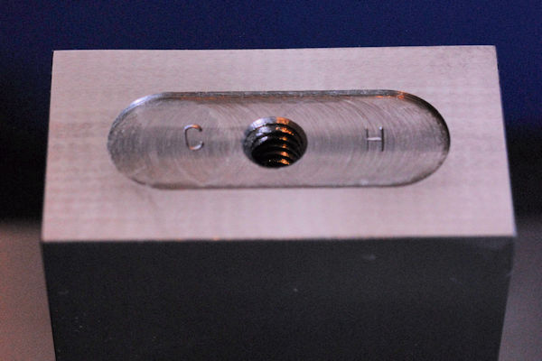
Relieve the central area of one end, the base, so it won't have any tendency to rock. It may take some effort to get the end square, multiple cuts or grinding passes, so make the relief about 0.05" deep. You want enough depth so that even if it takes a few trials to get the square square, you won't hit bottom. I drilled and tapped a 1/4-20 hole in the center, in case the square needs to be attached to some surface, or a bar added to create a regular square. You can stamp your initials on either side of the hole in the relieved area if you like.
People that are good at scraping will consider this a perfect project. I say if you have or can get access to a surface grinder, you'd be crazy not to use it. Nothing quickly generates parallel surfaces like a surface grinder, and parallel reference faces are the key to this tool. Using whatever means are at your disposal, make the reference surfaces (the long narrow faces) parallel.
Check the reference surfaces on a surface plate with a "tenth" indicator. They should be parallel to better than 0.0001". If the grinder is good, you shouldn't see any error at all.
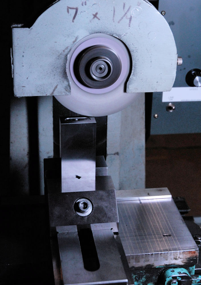
Now the fun part, finishing the relieved base and adjusting it to perfect squareness. I start by putting the square in a grinding vise and lining it up with a known "more or less" good square. Then I take a clean-up pass. If you're scraping, scrape it flat and check the squareness with a known OK square. This isn't the final adjustment, so we just want to get it close.
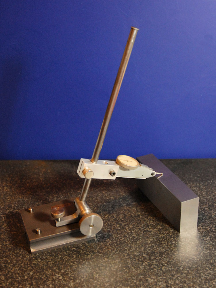
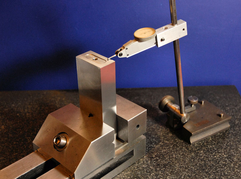
To bring the square as close to perfection as we can get it, we rely on the parallelism of the reference faces. With a tenth indicator set up as shown, zero on one of the reference faces. Rotate the square and measure the other face. If you've done everything well, it should be within a couple thou. The actual error is 1/2 of the reading.
The indicator tip must be directly above the lower contact point so the reading hits a maximum as you rock the base against the square. If the maximum occurs significantly off axis, move the indicator a bit left or right on the rod until you get the highest reading about square to the square.
Convert the error to in/in. Say the distance between the contact points is 4.5" and 1/2 the error is 0.001" That's 0.000222 in/in. Put the square back in the grinding vise (always same orientation) and indicate the top to that same slope, based on the width between the reference faces, and in the direction necessary to correct the error. Go back to the grinder and make another clean-up pass. In the photo I show the indicator perpendicular to the run being measured, but many indicators have some shift if used that way. Keep the indicator closer to parallel with the run being measured. If you're scraping, you know what to do.
Repeat the process, measure and regrind. You'll probably find it a challenge to do better than 10 arcseconds unless the base is quite long. It will take time, but the scrapers in the crowd can probably bring the error to less than 1 or 2 arcseconds.
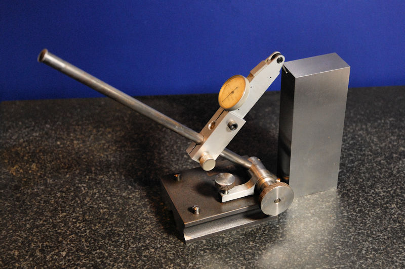
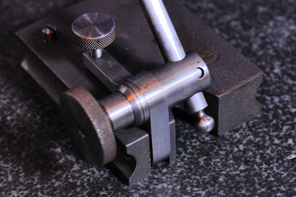
I saw the setup used above on the Practical Machinist forum. I don't know if the ball on the end of the rod was intended for the purpose, but it works well. That style of height scriber is old, but every bit as useful today as in the past.
If you do a Google image search, you'll find a few commercial and DIY comparators. The Taft-Peirce unit from Suburban Tool is impressive at $2560 as of this writing.
Note that square comparators invariably have a round lower contact point. This allows you to rotate the device against the reference square to maximize the reading. This arrangement is essential when using a cylindrical square. With the square above a flat lower contact could be used if desired, so long as full contact is maintained.
First, you can use the reference square to zero the square comparator, and then use that to measure the part in question on the surface plate. Note that even if your reference square is slightly off, a perfect zero is halfway between the two readings. This assumes the faces are parallel. This method gives you the exact amount the part in question is out of square.
Second, you can use the reference square exactly like any other square. Put a bright light behind it and judge the gap between it and the part. If the gap is large you can measure it with feeler gauges.
Finally, you can attach a flat bar to the reference square, assuming you added the tapped hole, and use it as a very precise internal or external square in the same manner as any other machinist's square.
I'd caution that since most won't use tool steel and have it hardened, the square is a bit subject to dings and dents. It should be stored in its own box and oiled to keep it from rusting, like most precision shop tools.
The name of the game is baseline. If you make this design larger, it becomes heavy and hard to handle. One possibility is to do the traditional frame or box square, hollow in the middle to reduce weight. An interesting design was pointed out to me that uses pinned bars, ground at the same time, forming a parallelogram. Crossed turnbuckles allow it to be squared to a high degree of accuracy. Long term stability might be lower, but it could be very good in the short term after adjustment.
As you go larger, it may be more difficult to grind perfectly straight surfaces at the travel limits of the grinder. Scraping could be required if the full accuracy expected from the size is to be realized.
A final thought I've had is to make the reference square as described, but start with a section of iron pipe. Say, 4" or so. There should be plenty of material to grind a 1" wide flat strip down each side. Leave the rest unfinished or clean it up as desired. Grind the base as described above. That should result in a higher accuracy verifiable square (longer baselines) with a low weight and at a very low cost.